
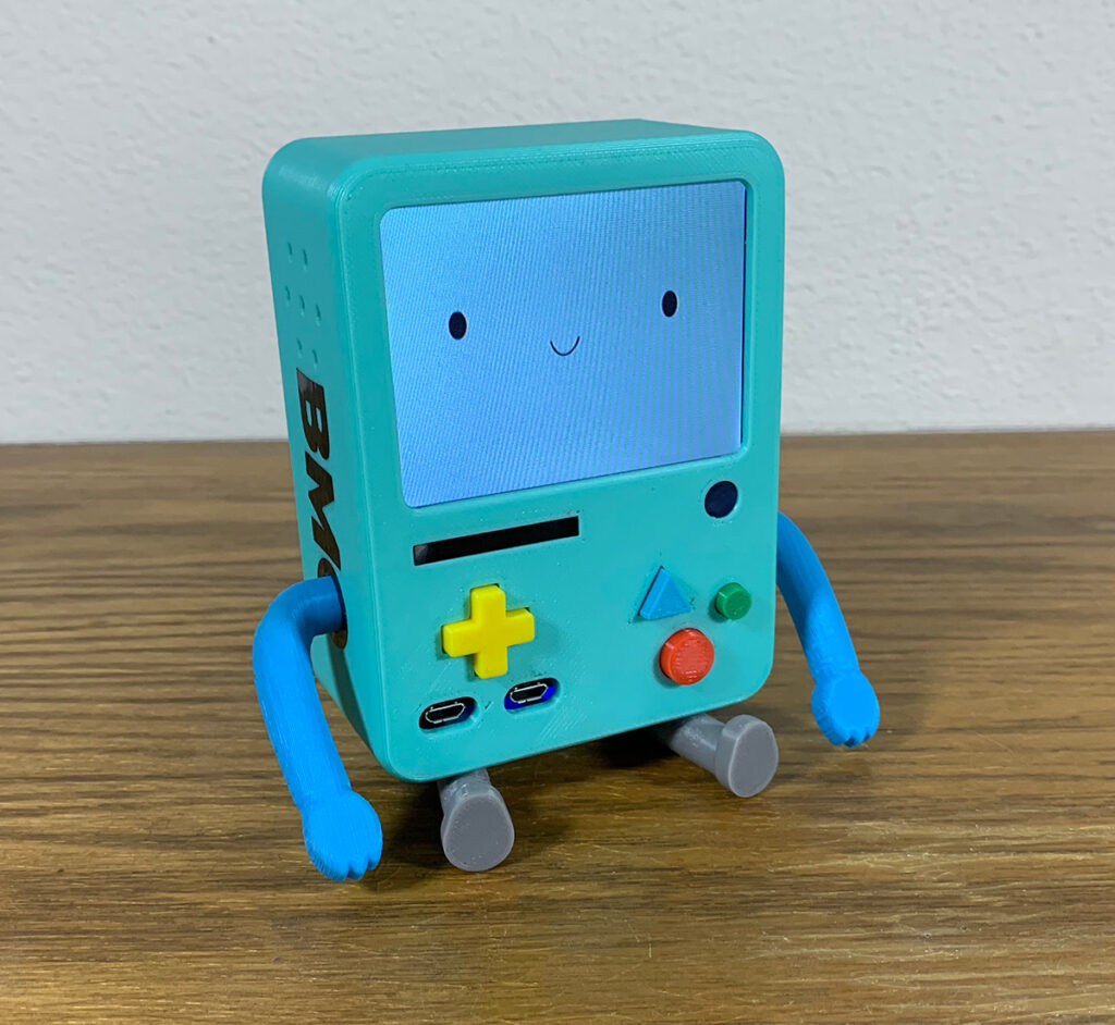
Let’s talk about what goes into a BMO-Boy. If you have been following along (mostly on YouTube) you are familiar with Big BMO. Big BMO is the full sized BMO that’s been around for a while. Building it is somewhat complicated and no two have ever been put together in exactly the same way. Then along came astroBMO which is on the ISS and you may have seen in the credit sequence for Distant Lands. Yes, BMO is really in space! BMO-Boy was spawned from the astroBMO project because it was easily 3D printed and I felt I could standardize the construction so anybody could build it. You can find the 3D model here: https://www.thingiverse.com/thing:4574341.
Once that is printed there’s a lot of stuff to cram in there. My YouTube channel details how to do that. I’m sure there are a few things that are difficult to see so I will try to detail them here when I can.
For starters, you need lots of electronics. Lots! This is a list for things you can buy online from AdaFruit, Amazon, or DigiKey. The tricky part is modifying the LCD which is detailed on the AdaFruit site and I have a video of how it’s done as well.
| PowerBoost 1000C | https://www.adafruit.com/product/2465 |
| Lithium Ion Battery – 3.7v 2000mAh | https://www.adafruit.com/product/2011 |
| Straight Mini HDMI Plug Adapter | https://www.adafruit.com/product/3552 |
| HDMI – 10 cm Ribbon Cable | https://www.adafruit.com/product/3560 |
| 3.5″ TFT | https://www.adafruit.com/product/913 |
| Pi Zero | https://www.adafruit.com/product/3400 |
| Hitec/RCD HS-40 Economy Nano Servo | Amazon |
| M2 Brass Insert | Amazon |
| M2.5 Brass Inserts | Amazon |
| Speakers | Amazon |
In addition to the off the shelf electronics, you will need some boards that I designed to be mounted inside the BMO case. Theses add: front panel USB ports, front panel buttons and DPad, I2S microphone, on/off switch, low battery indicator, power on indicator, charging port, external HDMI port, I2S audio out, 4 port USB hub, servo controller, composite video out. That was a lot of stuff to cram into a small space and I just couldn’t find anything off the shelf that would work. You can buy all that from AdaFruit but it just won’t fit. Trust me, I tried.
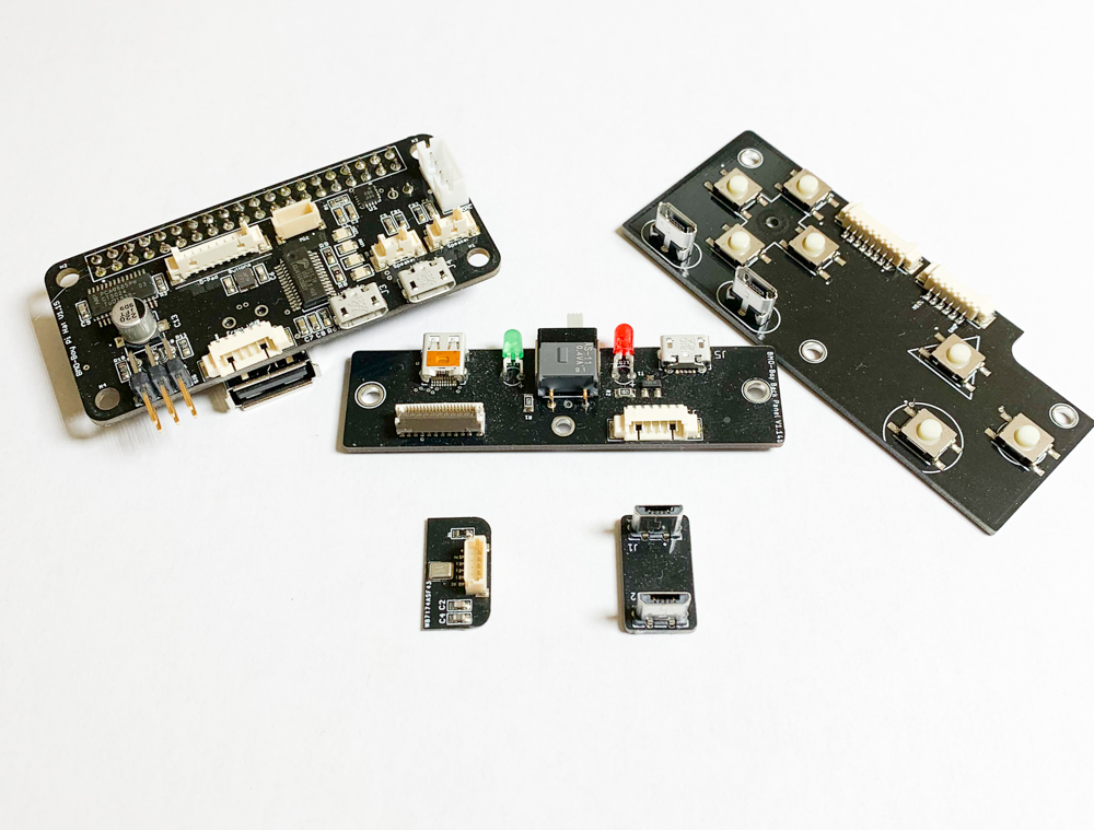
These can be found in my shop when they are available.
https://byobmo.com/?product=bmo-boy-circuit-boards
I’ve been slowly adding them as they become available. If there is a big enough demand I can get a larger run made. Right now I’m just trying to gauge interest.
Once you have all that stuff here is what it should look like.
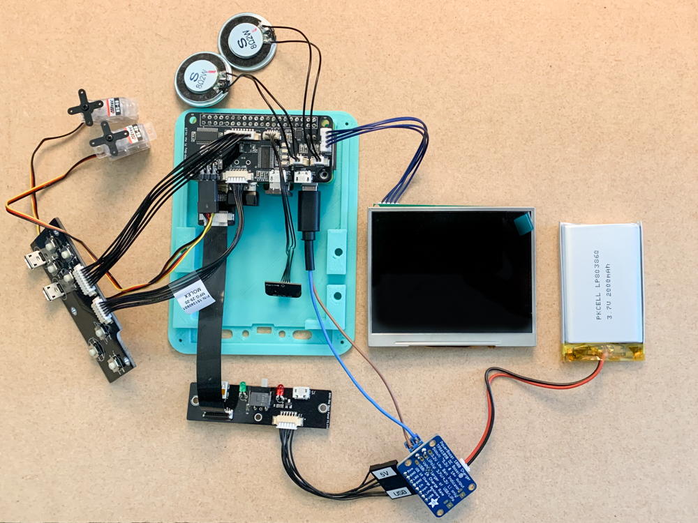
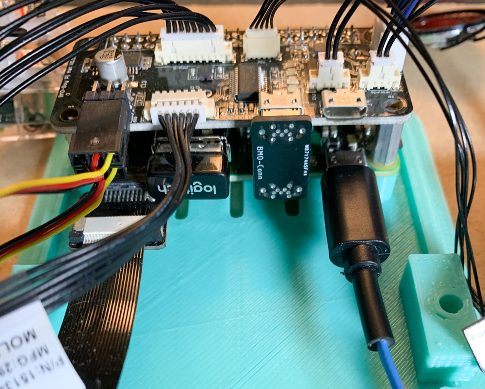
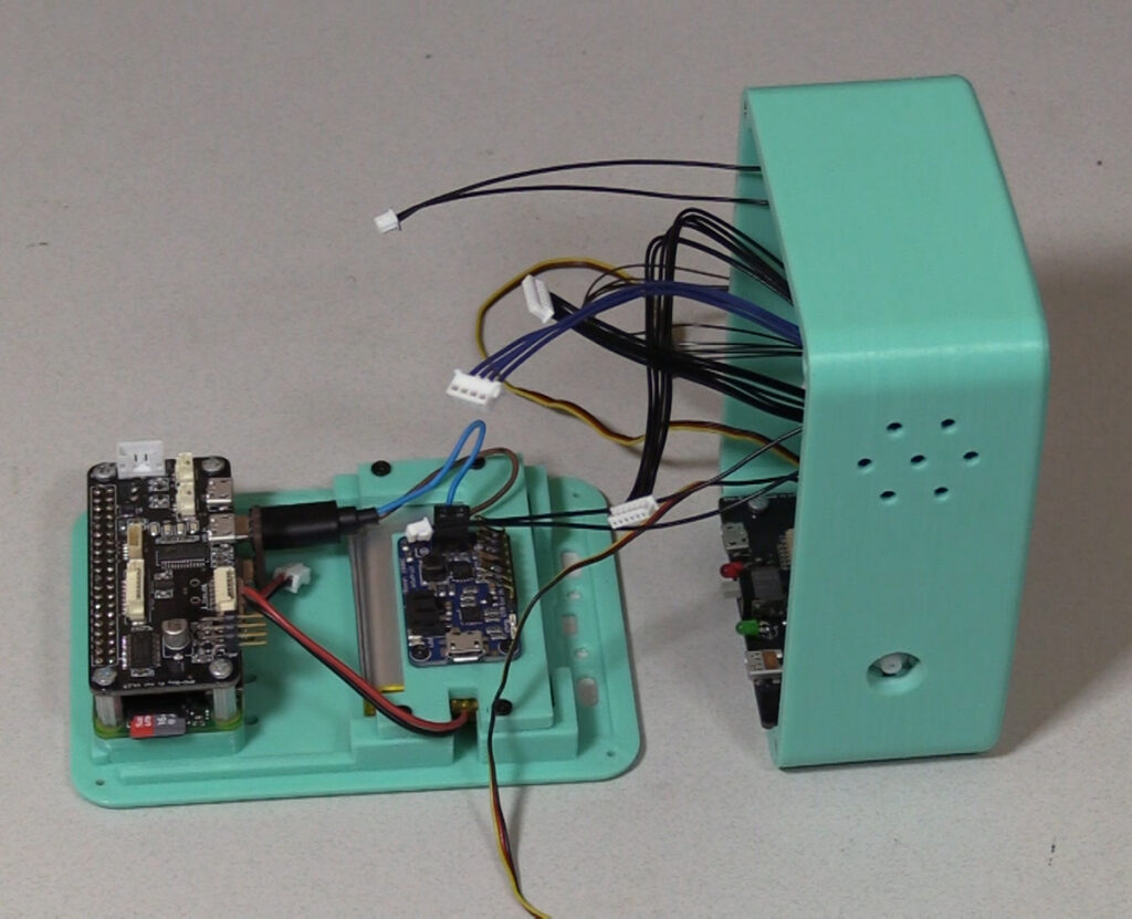
The Pi board sits on top of the Pi Zero with 11mm standoffs. Make sure the header on your Pi Zero isn’t an extended header or it won’t seat correctly on the 11mm standoff and the USB connector won’t fit. The USB connector is the small board with two USB micro connectors that connects the Pi Zero’s USB port to the input port of the expansion board. This enables the USB hub.
If you aren’t planning on using the HDMI micro port for desktop use then you can omit the FPC cable and the USM mini adapter. Saves some money but it is kind of cool. For me, it helps with debugging because it’s nice to have a large screen to work on.
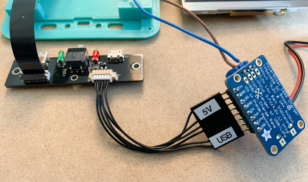
Connecting the PowerBoost to the Pi Board can be a problem if you reverse the connector. The end that connects to the Pi Board is a keyed Molex connector so that’s not a problem. The PowerBoost uses a standard pin header that you solder on so you have to make sure the wires aren’t crossed. The cable that I provide should be marked with a 5V and a USB which correspond the the 5V pin and the USB pin marked on the PowerBoost. Again, always verify.
You will also need a power cord that connects the PowerBoost module to the USB power port of the Pi Zero. I take a typical USB charging cable and cut it, strip the wires, tin the leads and use that for power. I don’t like using data cables because they have four wires to sort out and the wire gauge tends to be thinner. Either way, you need to verify which wire is positive and which is negative before connecting. I plug the other end (the part I cut off) into a USB battery and verify the leads with a multimeter. Rarely are the leads red and black and even when they are I have found them to be reversed at times. That’s bad news, so always verify. And then verify again.
Once all that is set up then you need software. I’ll detail that in another post. But the short version of it is I take a standard Raspberry Pi OS, add RetroPie, then add my custom BMOS.